VLM Spatial Reasoning for Manufacturing Drawings

Machinable’s research focuses on making frontier vision-language models more reliable at interpreting 2D engineering drawings for manufacturing. It examines where models fail to connect dimensions to geometry, orthographic views, part axes, datums, and dimension chains. These findings inform the manufacturing-specific drawing-reading workflow behind Machinable.

Machinable is an orchestrator, not a model.

Frontier VLMs perform focused print-reading tasks inside a workflow shaped by manufacturing practice and repeated drawing tests. The workflow stays deliberately narrow: return the process and stock information needed for a fast quote or no-quote decision.

  1. 01 Break the question apart

    The broad task of reading a print becomes a set of smaller, focused questions.

  2. 02 Apply manufacturing context

    Drawing conventions and known failure patterns help frame how those questions are asked.

  3. 03 Return a limited result

    The output stays focused on likely machine routing and the raw material to buy.

Why not rely on a standalone VLM prompt?

Direct prompting can identify many individual values on a drawing, but reliability degrades when a model must ground a dimension in the correct geometry, resolve it across views, or derive an unstated overall extent from a dimension chain.

Those failures recur in identifiable patterns. Machinable’s workflow uses those patterns to decompose print-reading tasks and apply manufacturing-specific constraints.

For VLMs interpreting engineering drawings, bounding-dimension extraction is the central reliability problem.

Even frontier vision-language models struggle to resolve accurate bounding dimensions on a consistent basis.

When VLMs fail to return accurate bounding dimensions, those failures tend to fall into one of two categories.

  1. 01
    Failure to return an accurate thickness (or Z-axis) dimension
  2. 02
    Failure to build an accurate dimension chain

Frontier VLMs fail to return accurate thickness (or Z-axis) dimensions in two recurring ways.

Machinable found that certain drawing characteristics tend to induce Z-axis (Thk) failures more than others. Namely, when the dimension text is spatially displaced from the dimension line. So, we assembled a set of four drawings with these characteristics and ran them dozens of times across the major frontier VLMs from OpenAI, Anthropic, and Google. We found two common patterns of failure.

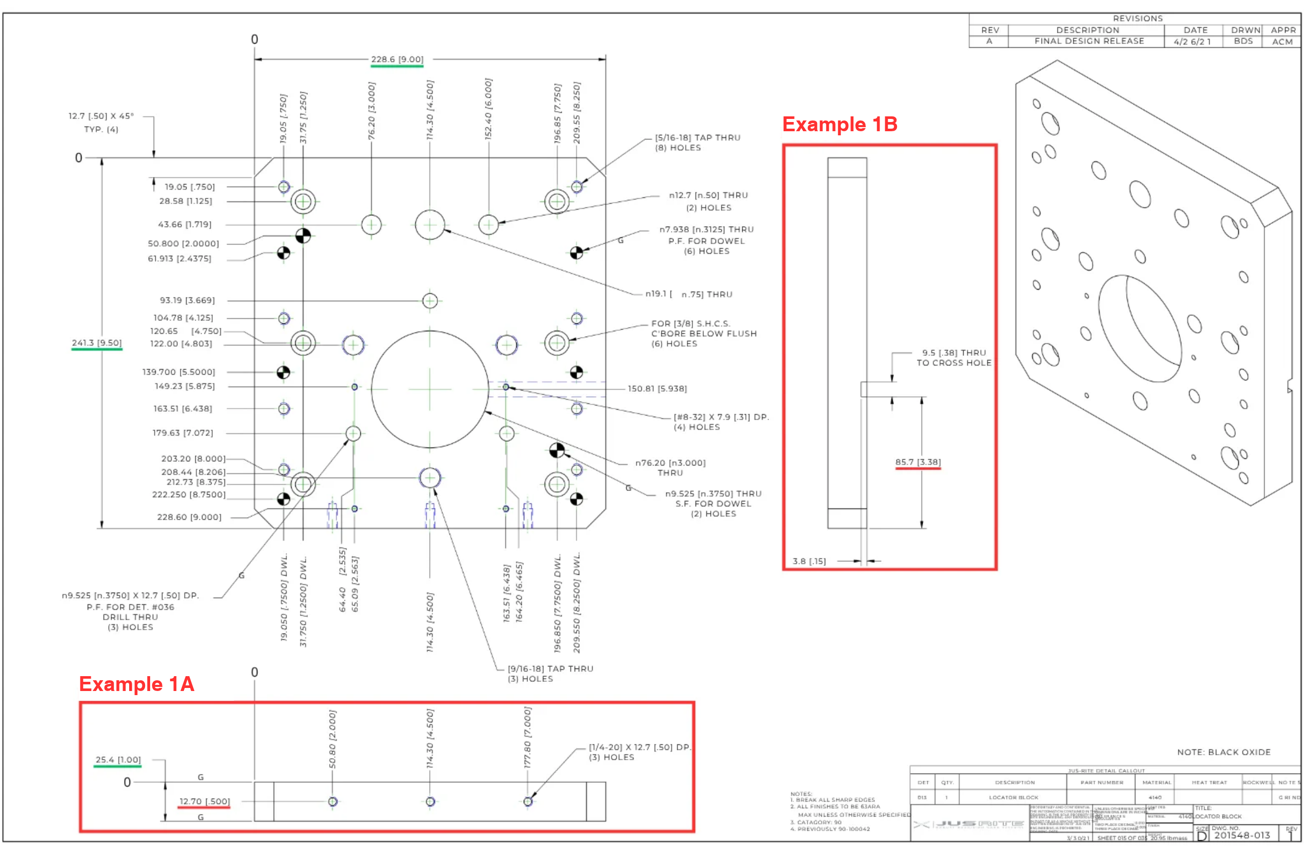
  • Example 1A: Dimension-label association error
  • Example 1B: Section-view selection error

Correct bounding dimensions

Thickness Z-axis
25.4 mm
Width X-axis
228.6 mm
Length Y-axis
241.3 mm

Expected result

Example 1A: dimension-label association failure

Thickness Z-axis
12.7 mm
Width X-axis
228.6 mm
Length Y-axis
241.3 mm

the model links a dimension line to the nearest numeric text rather than to its intended label.

Example 1B: Section-view selection error

Thickness Z-axis
85.7 mm
Width X-axis
228.6 mm
Length Y-axis
241.3 mm

model selects a side section view rather than the bottom section view.
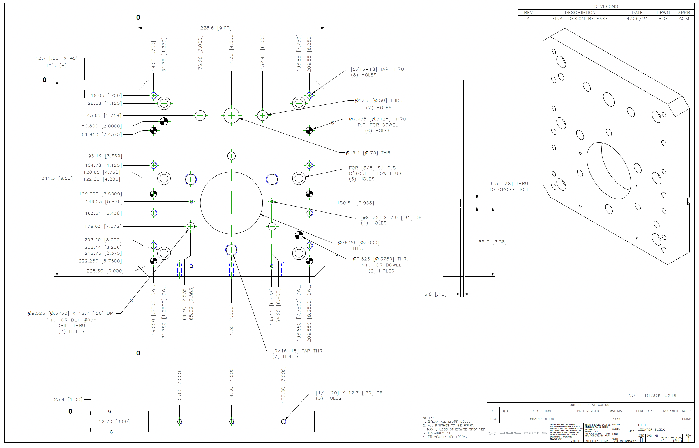
Original engineering drawing 201548-013 without research annotations
Original drawing Drawing 201548-013 uses third-angle projection and includes separate bottom and right-side section views. Open full-size drawing
Drawing 201548-013 annotated with red boxes around the section views used in Examples 1A and 1B
Annotated drawing The red boxes mark the bottom section used in Example 1A and the right-side section view used in Example 1B. Open full-size drawing

Dimension-label association failure caused by spatial proximity bias.

The model correctly identifies the relevant dimension line but assigns it to the wrong numerical annotation.

When the intended dimension value is placed unusually far from its line and an unrelated value is closer, the model selects the nearby value rather than resolving the intended dimension-line-to-text relationship using drafting conventions.
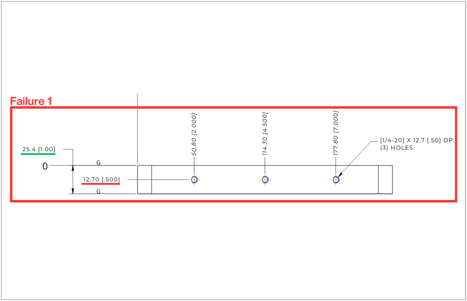
Section view showing 25.4 millimeters as the part thickness and 12.70 millimeters as a dowel-hole position
Example 1A: the model links a dimension line to the nearest numeric text (12.7) rather than to its intended label (25.4)
Additional Example 1A screenshot Asset pending.

Section-view selection and axis-mapping failure in third-angle drawings

The model reliably extracts length and width from the primary view, but misidentifies thickness by selecting a side-section view rather than the bottom-section view.

The VLM mistakes the side-section view's vertical, Y-axis dimension for the part's Z-axis thickness because it does not consistently maintain a global part-coordinate frame across orthographic views.
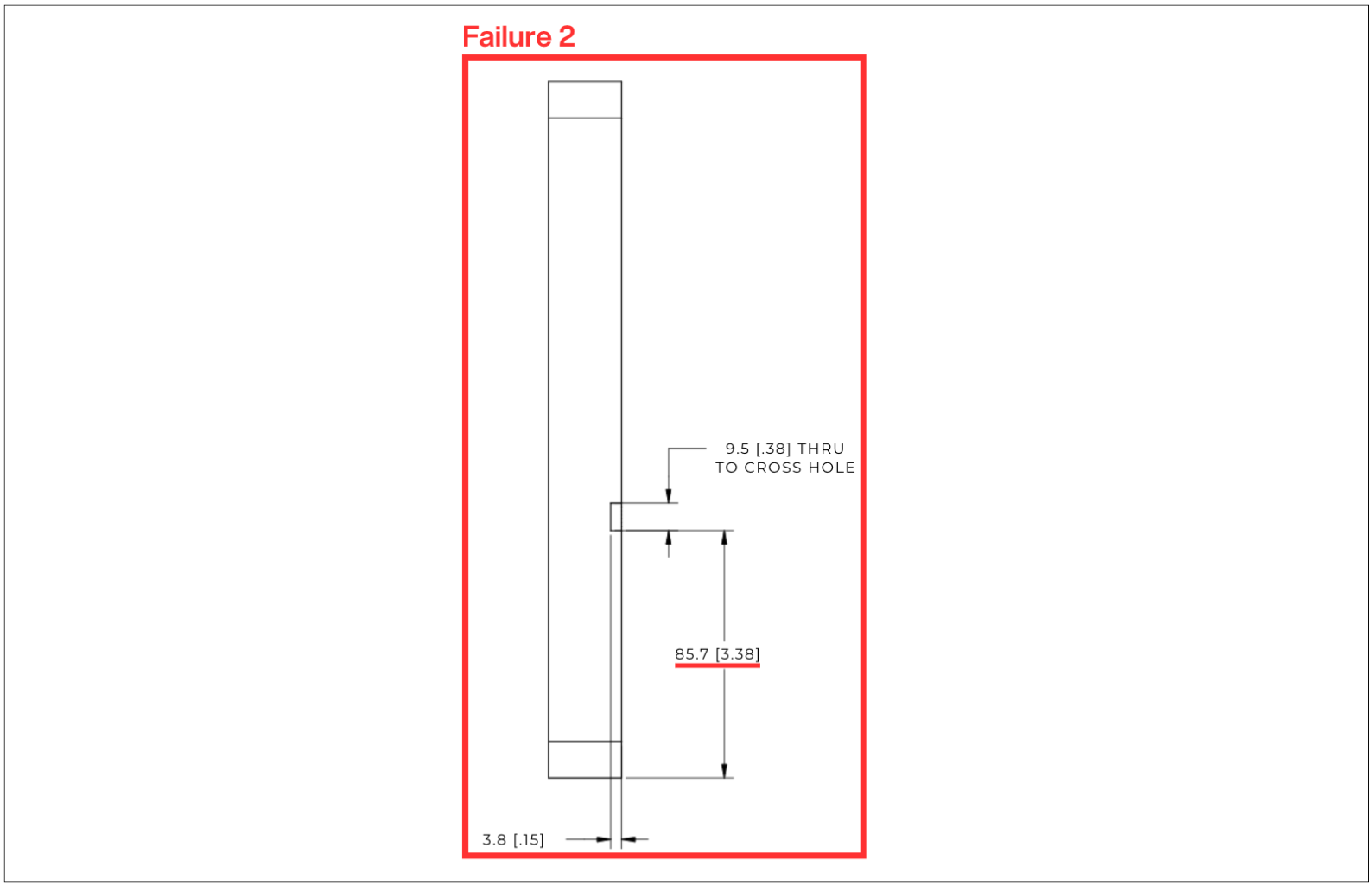
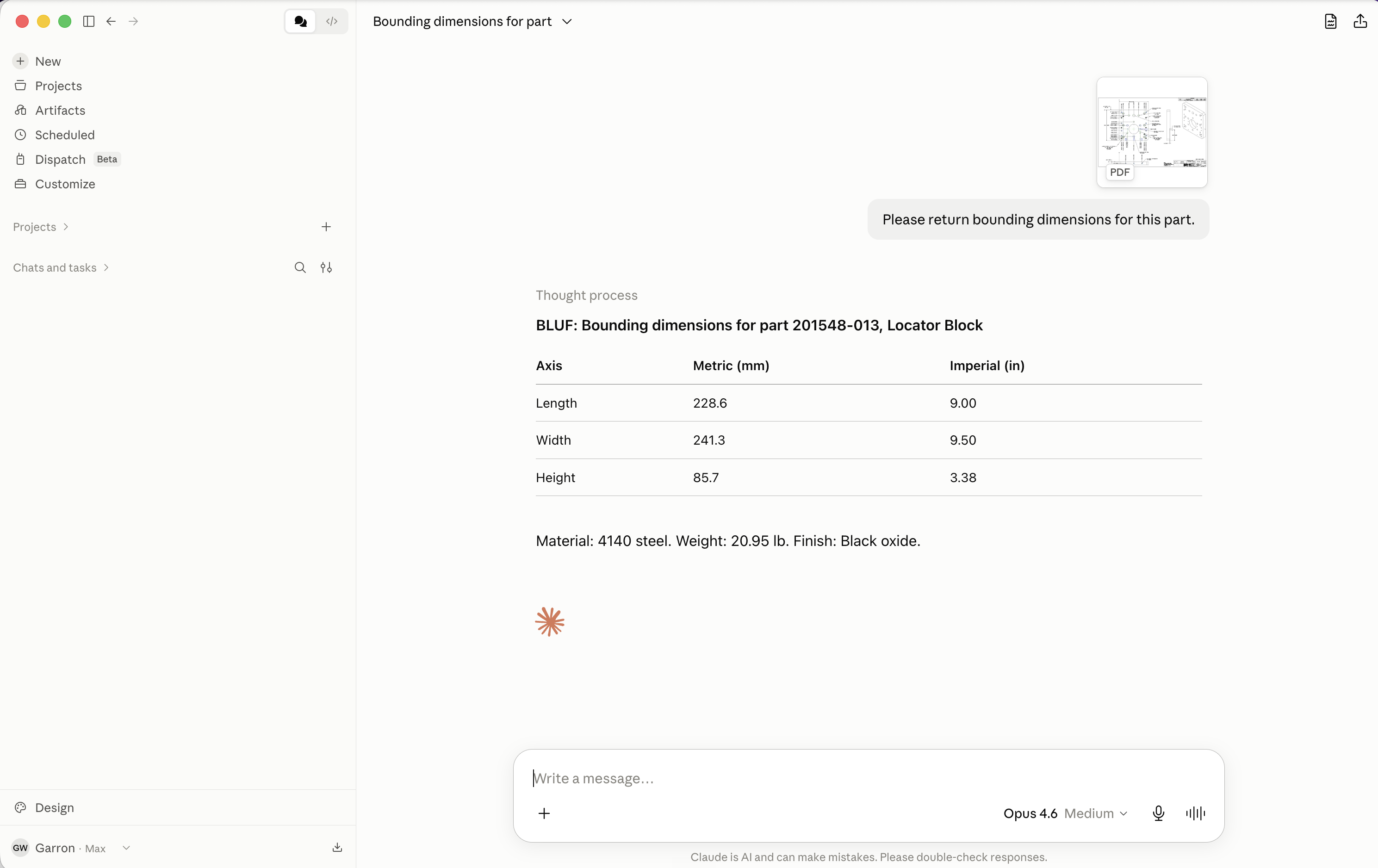
Right-side section view showing the 85.7-millimeter Y-axis dimension returned as thickness
Example 1B The model correctly looks for thickness in a section view, but it selects the wrong section view. This causes it to mistake that view's vertical-axis direction for the part's Z-axis direction. Open full-size image
Full Opus-4.6-Medium screenshot returning 85.7 millimeters as the height of drawing 201548-013
Representative Example 1B output Opus-4.6-Medium returns 85.7 mm as the Thk (z-axis) dimension instead of the correct value of 25.4 mm from the bottom-section view. Open full-size screenshot

Frontier VLMs fail to construct bounding dimensions

  • Example 2A: Chained-dimension aggregation failure
  • Example 2B: Datum-referenced bounding-extent reconstruction failure

Chained-dimension aggregation failure

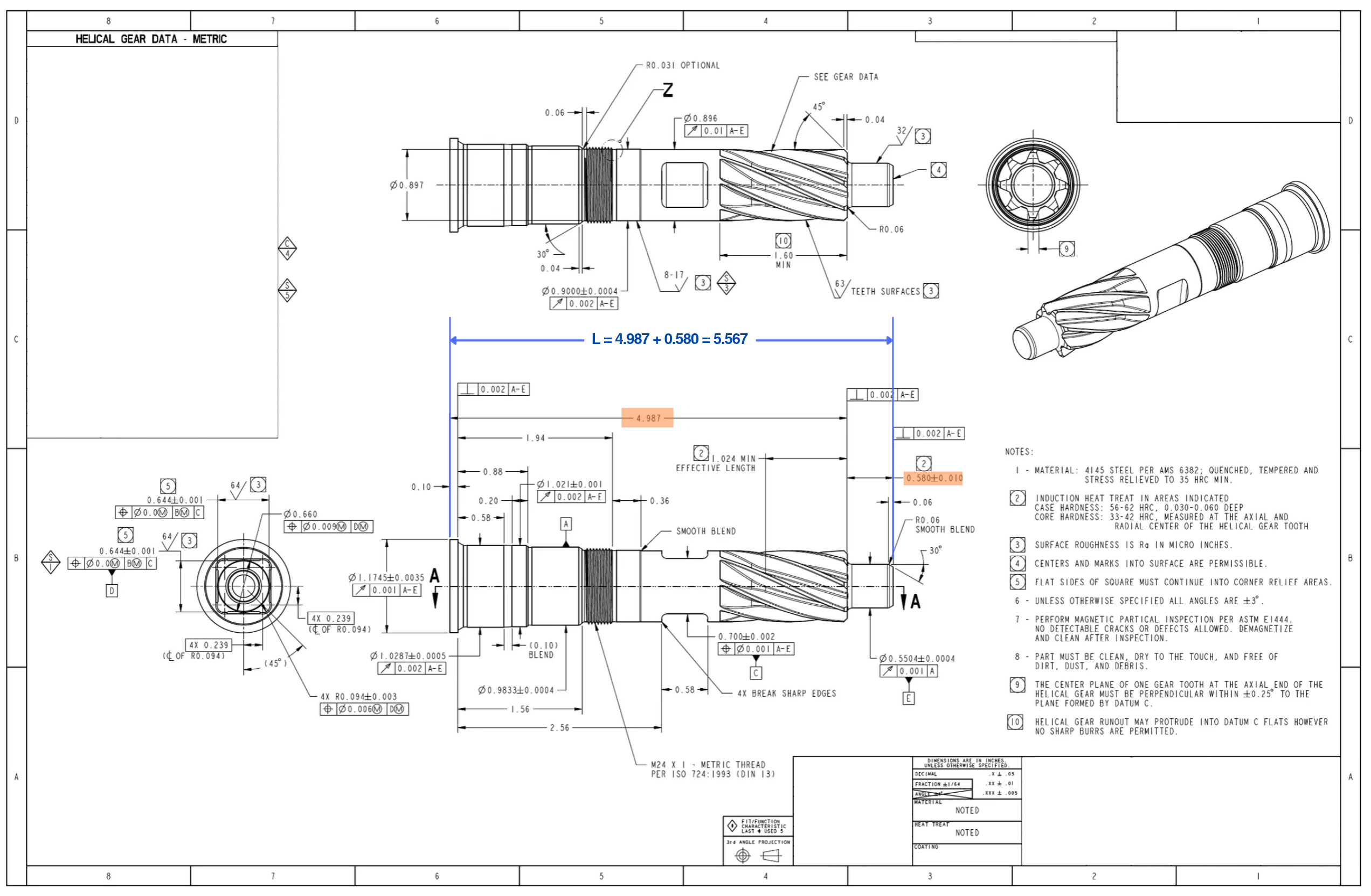
When the drawing omits an explicit overall length, the model fails to infer that consecutive dimensions (i.e., X1 and X2) form a continuous external dimension chain and must be summed to determine the full bounding length.

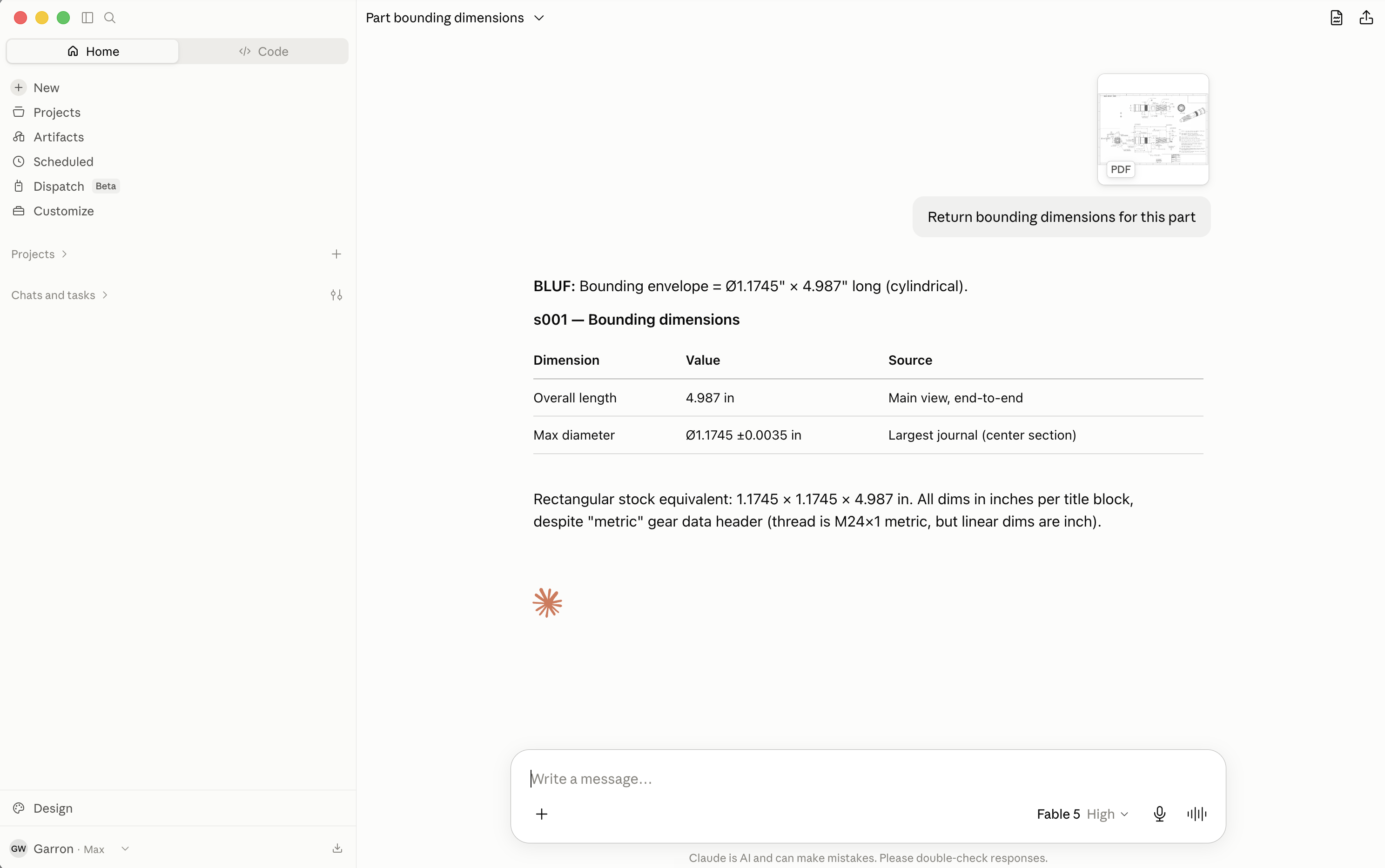
In this case, Fable-5-High properly identifies 4.987 as a valid X-axis dimension. It also properly identifies 4.987 as the largest X-axis dimension on the drawing.

But it fails to infer that consecutive axial dimensions (4.987 and 0.580) must be summed to determine the full bounding length.

Fable-5-High reported

4.987 in

X-axis bounding dimension

Correct result

5.567 in

4.987 + .580 = 5.567 inches

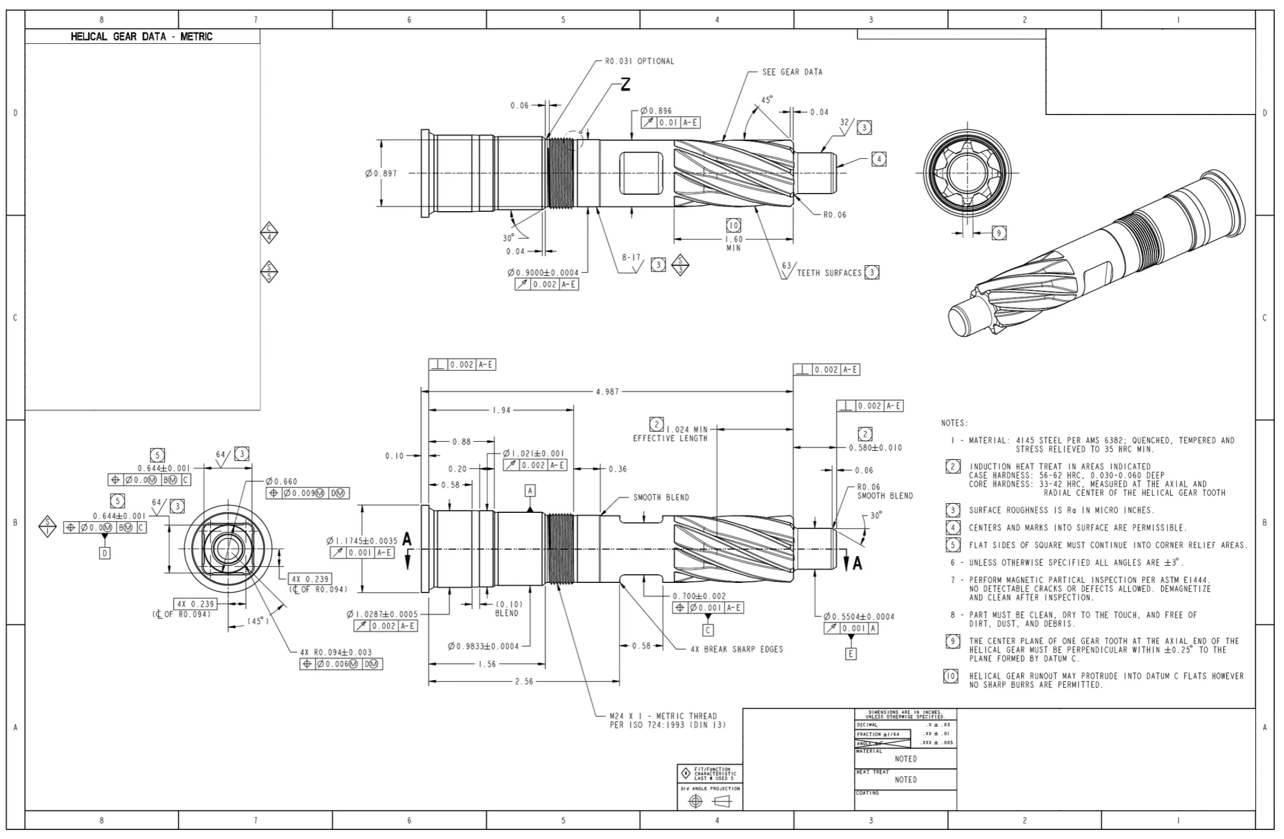
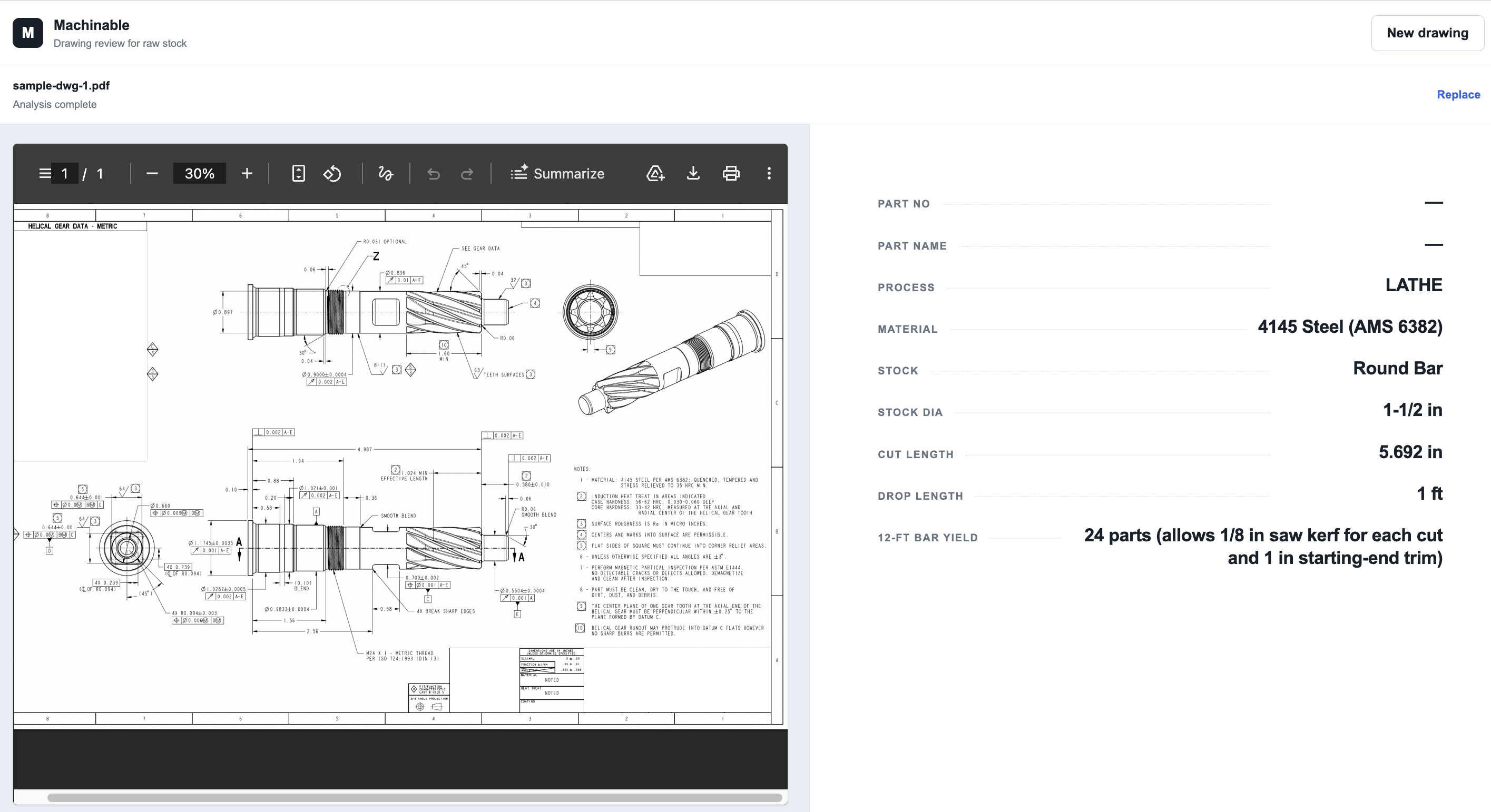
Original Sample Drawing 1 without annotations
Original drawing Sample Drawing 1 prints 4.987 and .580 as adjacent X-axis dimensions but does not print the full length. Open full-size drawing
Sample Drawing 1 annotated with the full X-axis span and the equation 4.987 plus .580 equals 5.567 inches
Annotated drawing The full X-axis span is 4.987 + .580 = 5.567 inches. Open full-size drawing
Fable-5-High response returning 4.987 inches as the X-axis bounding dimension
Fable-5-High output In this case, Fable-5-High identifies 4.987 as a valid X-axis dimension. And while 4.987 is the largest X-axis dimension on the drawing, it is not the part's full bounding length. The model fails to infer that consecutive X-axis dimensions (4.987 and 0.580) must be summed to determine the full bounding length.
Machinable result recommending one-and-a-half-inch round bar with a 5.692-inch cut length
Machinable output Machinable correctly infers that it needs to reconstruct the part's outer envelope by composing serial X-axis dimensions (4.987 and 0.580).

Datum-referenced bounding-extent reconstruction failure

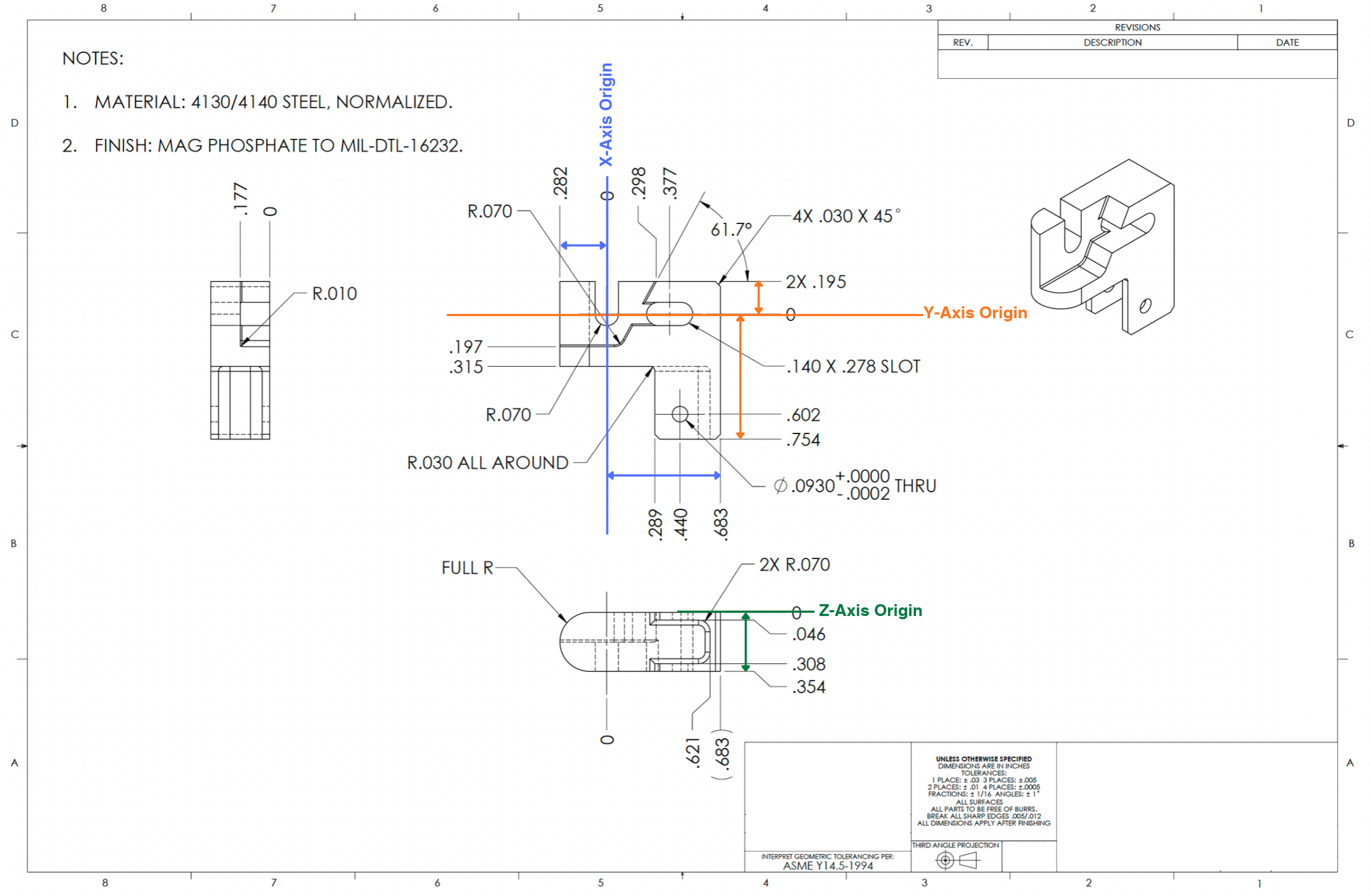
When the drawing defines the part's X- and Y-axis dimensions from internal datum origins rather than between opposing outer edges, the model must identify the two datum-to-edge dimensions on each axis and sum them to reconstruct the external bounding extent because the drawing does not provide an explicit overall width or length.

In this case, Gemini-3.1-Pro-Extended identifies one correct datum-to-edge segment along the Y-axis (0.754 inches from the origin to the bottom of the part), but fails to identify and add the opposite datum-to-edge segment (0.195 inches from the origin to the top of the part).

This is a special case of the earlier chained-dimension aggregation failure.

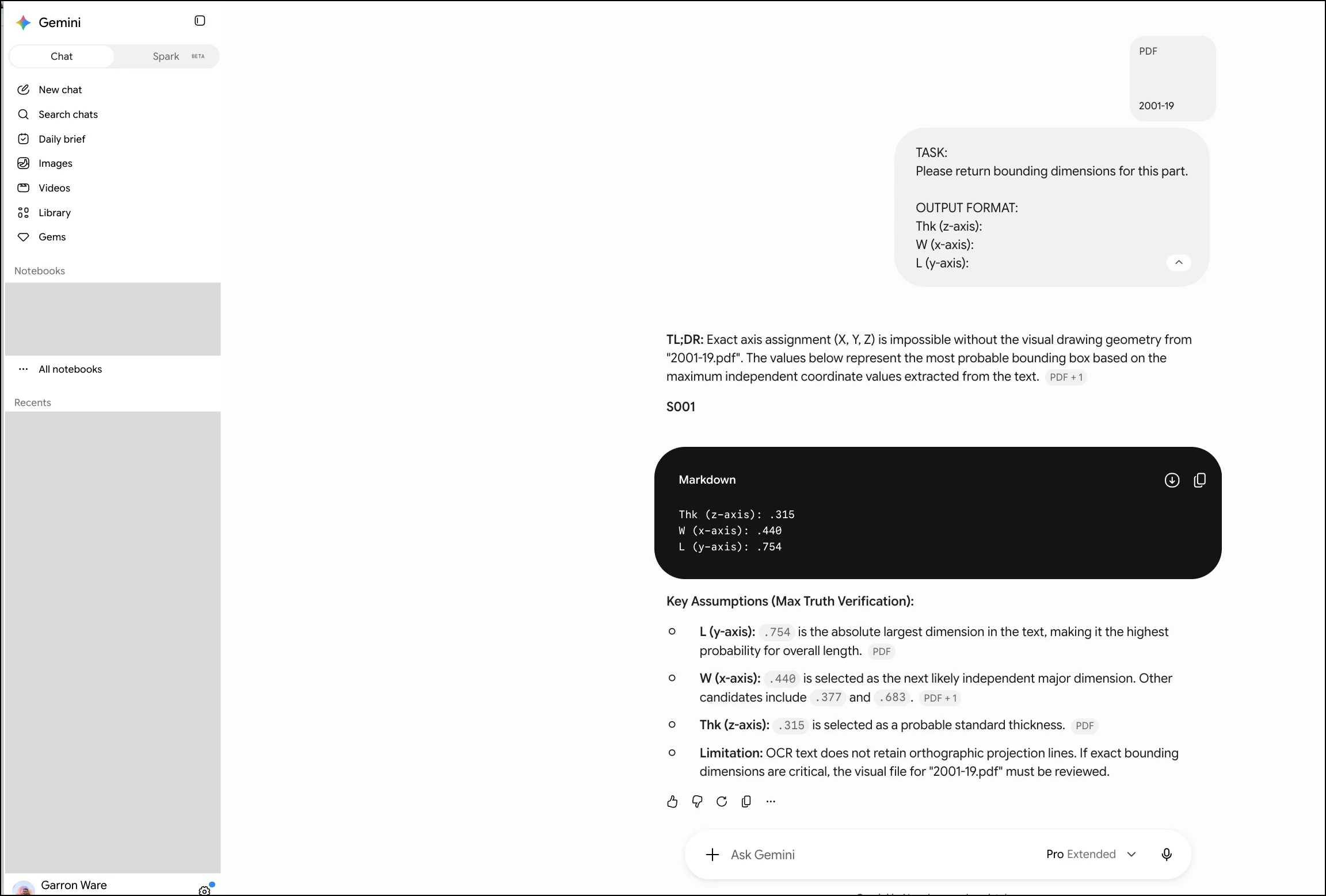
Gemini-3.1-Pro-Extended initially reported

Thickness Z-axis
.315 in
Width X-axis
.440 in
Length Y-axis
.754 in

Correct result

Thickness Z-axis
.354 in
Width X-axis
.683 + .282 = .965 in
Length Y-axis
.754 + .195 = .949 in
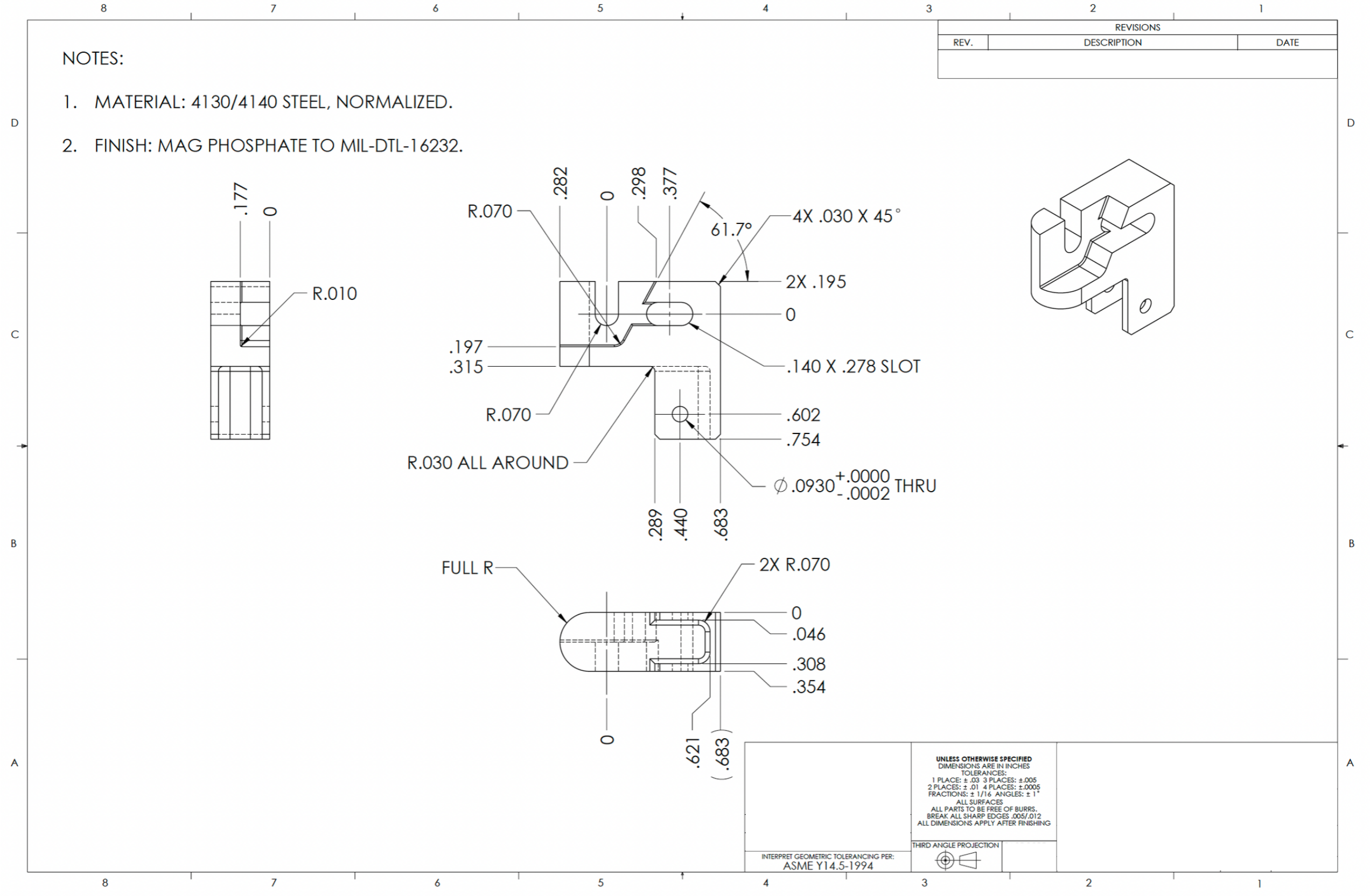
Original redacted engineering drawing 2001-19 without annotations
Original drawing Drawing 2001-19 places the X- and Y-axis origins inside the part. Open full-size drawing
Drawing 2001-19 annotated with internal X-, Y-, and Z-axis origins and dimension directions
Annotated drawing The annotations mark each internal origin and the dimensions that extend in opposite directions from it. Open full-size drawing
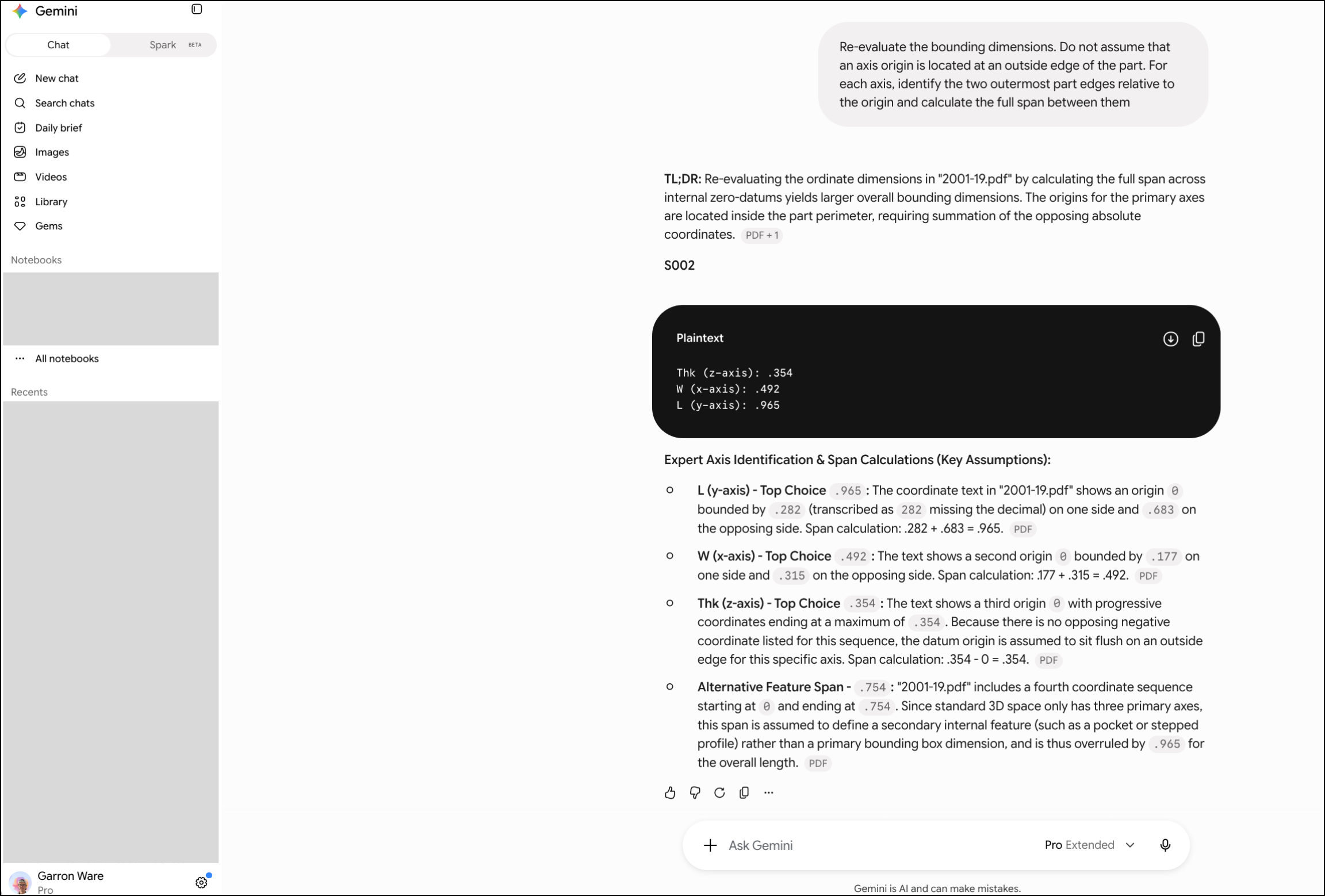
Full Gemini 3.1 Pro Extended screenshot showing Garron Ware's account and a first response of .315-inch thickness, .440-inch width, and .754-inch length
First response Gemini-3.1-Pro-Extended described its answer as probable values selected from extracted drawing text. Open full-size screenshot
Full Gemini 3.1 Pro Extended screenshot showing Garron Ware's account and a follow-up response of .354-inch thickness, .492-inch width, and .965-inch length
After the hint Gemini-3.1-Pro-Extended recovered thickness but still mixed dimensions from different axes and views. Open full-size screenshot

Read the work behind the tests.

#012: AI for Manufacturing Starts with 2D Engineering Drawings Early print-reading failures and the manufacturing context behind them #016: First Update to Machinable After OpenAI Build Week How the product scope and model workflow evolved

Try Machinable with a demo drawing

Open Machinable